Transformer Windings Resistance Tests
2023-02-16
Transformer Windings Resistance Tests
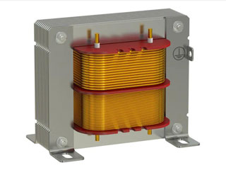
Winding resistance measurements are an important diagnostic tool to assess potential damage to transformers as a result of poor design, mounting, handling, unfavorable environments, overloads, or poor maintenance.
The main purpose of this test is to check for large differences between the windings and for gaps in the connections. Resistance measurement ensures that each circuit is wired correctly and all connections are secure.
Resistance will change due to shorted turns, loose connections, or deteriorated contacts in tap changers. Regardless of the configuration, resistance measurements are normally made phase-to-phase and the readings are compared with each other to determine if they are acceptable.
Resistance measurements are obtained by passing a DC current through the winding under test and measuring the voltage drop across each terminal (Ohm’s Law). Modern test equipment for this purpose uses a Kelvin bridge to achieve results.
 Test Equipment Connection
Both the primary and secondary terminals of the transformer must be isolated from external connections and measurements must be made on each phase of all windings. Test equipment connections should be made in the following order:
Ground: The transformer should first be grounded directly to the local station ground and then connected to the test equipment ground. Necessary accessories such as remote controls, warning beacons, PC, etc. should be connected here.
Test Leads: With the test leads disconnected from the device under test, connect the current and voltage leads to the test equipment and check the tightness of all connections.
Transformer – Each transformer configuration requires different test connections. Special care must be taken to prevent the leads from being dropped during the test or from being connected on top of or too close to each other. The voltage cables must always be placed inside (between) the current cables and the transformer.
Input power: connect test equipment. Before making this connection, ensure that the power supply ground has a low impedance path to the local station ground.
Connection of the transformer under test
It should be noted that each transformer configuration is different and your specific configuration may not apply to what will be explained below, the user manual that came with the test kit should be consulted for more information.
.jpg) Obtaining Winding Resistance Measurements
Obtaining Winding Resistance Measurements
When measuring winding resistance, the reading should be observed and recorded once the resistance value has stabilized. The resistance values will “drift” at first due to transformer inductance, which is more common in large delta-connected windings.
For small transformers, the drift lasts only a few seconds; for single-phase high-voltage transformers, the drift can last less than a minute; for large transformers, the drift time required could be a couple of minutes or more. Any change in current will cause the resistance value to change.
Tap Changer Winding Resistance
Many power and distribution transformers are equipped with tap changers to increase or decrease the turn ratio depending on the supply voltage. Since the ratio change involves a mechanical movement from one position to another, each tap must be verified during a winding resistance test.
For “off-load” taps, the transformer must discharge between tap changes. “On-load” tap-changers and voltage regulators can be operated with the test set on while switching from tap to tap, this not only saves time but can also verify the closing function before the changer is interrupted of shots
Test Results
Interpretation of winding resistance results is generally based on a comparison of each resistance value with each adjacent winding on the same tap. If all readings are within one percent of each other, the sample is considered to have passed the test.
Comparisons with original factory measured test data may also be made using temperature corrected values, keeping in mind that field endurance tests are not intended to duplicate the manufacturer’s test record, which was likely performed on a controlled environment at the time. of manufacture.
Sample Test Data
Depending on the size of the
transformer winding under test, resistance readings will be expressed in ohms, milliohms, or microohms.
Temperature Correction
Since resistance is temperature dependent, corrected values should be used whenever results are compared with trend data. It is more important to estimate the winding temperature at the time of measurement.
If the transformer has a winding temperature gauge, these readings can be used; otherwise, the winding temperature is assumed to be the same as the oil temperature. If the transformer is measured without oil, it is normally assumed that the winding temperature is the same as the surrounding air.
The measured resistance should be corrected to a common temperature, such as 75°C or 85°C, using the following formula:
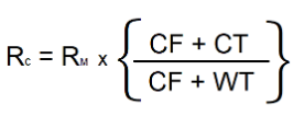
RC = corrected resistance
RM = the measured resistance
CF = correction factor for copper (234.5) or aluminum (225) windings
CT = corrected temperature (75°C or 85°C)
WT = winding temperature (°C) at the time of the test
Transformer Demagnetization
Once all the tests are completed, the demagnetization operation must be performed on the transformer. This step is essential for smooth operation when commissioning the transformer.
If a demagnetization operation is not performed, excess residual flux in the transformer core can cause large inrush currents on the primary side that could trip the protection relays. Transformer demagnetization is accomplished by passing multiple cycles of reduced current through a winding in both the positive and negative (alternating DC) directions.
Demagnetization should only be performed on a single winding after all resistance tests have been completed. When modern test equipment with demagnetization function is used, it is recommended that the current and voltage leads be connected to a high side winding for the demagnetization process.
For current transformers, run a saturation test to demagnetize the CT upon completion of all winding resistance tests.


